12/02/2008
11/18/2008

10/22/2008
Yes, the welder is back in action!
After a special order, 2 weeks of waiting and 30 confusing minutes at the welding supply store I managed to get a new flow gauge for my regulator. It's the big one on the left.

And here's a little progress:


And here's a little progress:

9/24/2008
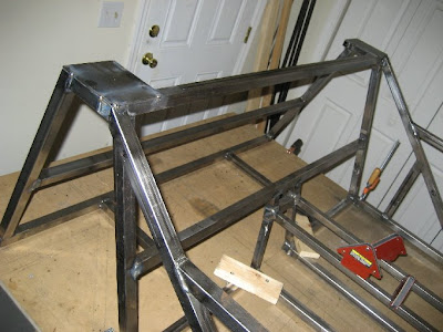
Roll bar platforms
Here are the frames for the platforms:

The frames welded into place:

Another angle:

Finished (well, this still needs to be fully welded) with some 1/8" plate on top:

Eventually the main roll bar hoop will mount across the top of these two platforms. Also, hopefully I'll be able to use the bottom of each platform as the upper mount point for each rear shock.
Why I couldn't finish welding... this thing is broke:

I noticed that when making some of my tack welds something was sounding a little funny, so I rechecked all the settings on the welder. When I went to check the gas flow rate, this gauge read zero (well, actually it read less than zero because the needle was bent and could go past the stop-- it looks like I must have whacked it at some point). There was definitely gas coming out of the weld nozzle-- and I could definitely adjust it-- but I can't set it to the correct rate. So, I'm thinking this thing must be broken. Hopefully it won't be too difficult to get a replacement.

The frames welded into place:

Another angle:

Finished (well, this still needs to be fully welded) with some 1/8" plate on top:

Eventually the main roll bar hoop will mount across the top of these two platforms. Also, hopefully I'll be able to use the bottom of each platform as the upper mount point for each rear shock.

Why I couldn't finish welding... this thing is broke:

I noticed that when making some of my tack welds something was sounding a little funny, so I rechecked all the settings on the welder. When I went to check the gas flow rate, this gauge read zero (well, actually it read less than zero because the needle was bent and could go past the stop-- it looks like I must have whacked it at some point). There was definitely gas coming out of the weld nozzle-- and I could definitely adjust it-- but I can't set it to the correct rate. So, I'm thinking this thing must be broken. Hopefully it won't be too difficult to get a replacement.
9/13/2008
The Rear End
Laying out the rear end... finally!


Building up from here:


It's not quite done yet, but this is a lot more progress than the 7 has seen in a while :)


Building up from here:


It's not quite done yet, but this is a lot more progress than the 7 has seen in a while :)
9/02/2008

5/20/2007
Rear Suspension Geometry
Okay, lets get technical. I've finally managed to get my suspension models working well (they're easier to use-- modify and see how it affects the suspension).
My initial design, as shown in an earlier post, was to mount the A-arms to the frame inside of the upper diff mounts. This however, wouldn't allow me to get the diff in and out of the frame. So, the following designs are based on mounting the upper A-arms outside of the upper diff mounts.
The models below are kind of a chronological progression as I worked through several different modifications to address particular issues. Each time I created a new model I gave it a letter to identify it. For sanity, I have only included selected models.
For each different model, I started with it at rest, and adjusted it until the the track width was near my target (64.5" for the rear) and the camber was near zero. Then I perturbed the model in 3 different ways: bump, droop, and roll. For each of these, I measured the absolute camber, track width and roll center position. These absolute values were then used to calculate the relative changes from rest.
rD: A place to start.
This model is based on a cursory identification of where the A-arms might have to be mounted to fit around the differential. The subsequent changes in other models are based on this one.

This model is alright. But it's got a lot of negative camber change in bump. Also, in droop the roll center follows the body up high. I'm afraid this might cause a problem with jacking.

rF: Moving the inboard lower link mount outward.
The lower link was shortened to accommodate this. The upper link length and mounting has not changed from rD.

This helped with the camber change in bump, but there is now more slightly more positive camber change in roll, and much more in droop. Also the roll center has gotten really high in droop. Neither of these is very good.

rH: Moving inboard lower link mount inward.
The lower link was shortened to accommodate this. The upper link length and mounting has not changed from rD.

This hasn't done anything to address the negative camber in bump, and has slightly increased the positive camber in roll. It has managed to stabilize the roll center though.

rJ: Increasing the inclination of the upper link from rH.
This was done by moving the inboard mount downward and lengthening the link.

This has greatly reduced the camber change in roll. But it has totally messed with the camber during both bump and droop. The negative camber change is absolutely out of control in bump. Most importantly though, the roll centers are just way too high here.

rK: Going back to rD, and decreasing the inclination of the upper link.
The inboard mounting location for the upper link has been moved upward to decrease it's inclination. It is now almost parallel to the lower link.

This has reduced the camber changes in both bump and droop. This is good. It has slightly increased the camber change in roll. The roll center is also very low. This might eliminate the possibility of jacking.

rL: Backing off a bit from rK.
Okay, so rK was looking good but this model just slightly increases the inclination of the upper link a little bit (so the upper an lower links aren't quite as close to parallel).

This model isn't as good at camber change in bump, but it is a bit better at reducing camber change in roll and droop. Also, the roll centers are nice and low (except in droop where it gets a little high).

Summary
I think I'm going to with something like rK or rL since they have low roll centers, minimal track width changes, and achieve a balance between camber change in bump and roll.
Also, none of this would have been possible without Carroll Smith's awesome book Tune to Win. If you're building your own suspension, you NEED this book.
Subscribe to:
Comments (Atom)