3/12/2007

A tough week.

Here's what I worked on this week... Costa Rica.


2/12/2007

A brief note about suspension design

It's complicated.

Okay, so I need to finish building the frame. But first I have to design the rear suspension so that I know where to build the inboard mounting points. And while I do that, I have to design the front suspension so that somehow they'll work together (as if I knew what I was doing).

From what I've been reading of Carroll Smith in Tune to Win, I think my major goals for the suspension are:
  1. Keep the laden (outside) wheel as vertical as possible during roll (without requiring gobs of negative camber at rest).
  2. Keep the track width as consistent as possible.
  3. Also, I'd like to be able to drive around without clipping the top of every 1/2 inch pebble.
I'm trying to not get too wrapped up in every possible detail that could affect the outcome of the design because:
  1. I really don't have any idea how certain features of the car are going to turn out... like the weight balance. And even if I did, I wouldn't know how these would interact with the suspension.
  2. There are just too many things to worry without going totally crazy.
So I just want to focus on a few parameters, build something I think might work and then try it out. Hopefully it'll be adjustable enough to work out minor problems, and if it's a total catastrophe, I can just redesign it (with my wealth of knowledge gained from having tried it once already).

Here's a sample of front suspension design layout:


Wow that image looks like garbage. I think my computer found out that I hate it.

I think I'll sleep with Mr. Smith's book under my pillow tonight-- maybe I'll wake up with the answers.

1/14/2007

Driveshaft tunnel

Okay, check it out... some actual progress. Here I am test fitting the engine in the frame again. This time I can actually mount it to the frame though.


An engine mount close-up. Everything fits together nicely.


With the engine back out again, it's time to get it back on the table and get to work.


Here's the first part of the driveshaft tunnel-- the bottom rails.


After cutting out the center of that rear cross-member, the differential can be test fitted to make sure that the driveshaft will have enough room inside the tunnel.

It's difficult to tell here, but the input to the differential is actually offset from the centerline of the car (towards the passenger-side) by about an inch. Since the output of the transmission is on the centerline, this means that the drive shaft won't run straight back to the diff-- it will have to be run at an angle. But, I consulted the oracle and he said it was okay. In fact, I shouldn't have the driveshaft running perfectly straight. Once everything is hooked up, the angle on both the front and rear u-joints should need to be about 3 degrees.


A little bit of string where the tunnel will be makes sure that everything will fit... before I start cutting any metal. I want to make the tunnel as narrow as possible so that I'll have enough room left over to fit a decent pair of seats.


The cut pieces that will make up the driveshaft tunnel. This is 3/4" 16 gauge square tubing.


The tunnel tacked into place:


Another angle:


I've run out of gas... literally. I'll need to stop at the welding store and pick up a fresh cylinder before I can fully weld this. There are a few more pieces to cut to completely finish the tunnel. Also, I need to fit the front differential mount in here some where.

1/06/2007

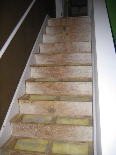
The stairs are finished!

Well, here they are. This ended up taking waaaay longer than I expected, but I think that they ended up looking pretty good. Now it's time to get back to working on the 7.


Dad, Meg and Erin-- Thanks for the HD gift cards. Here's what I got, first an 18V cordless drill set:


And also this big, honkin' drill press. It's got lasers:


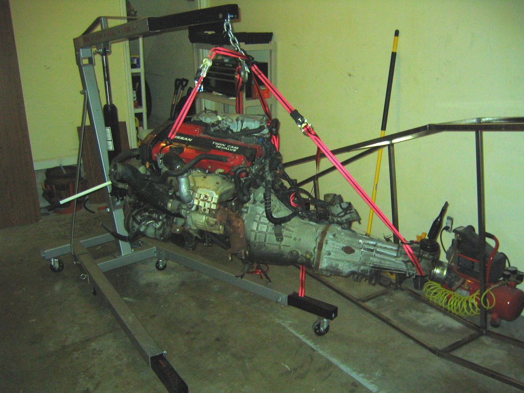
And, I finally got my own engine hoist. This is going to end up being a lot more convenient than borrowing one like before. Even though it's orange, it didn't come from Home Depot. Rather it came from the made-in-China-store.
12/16/2006

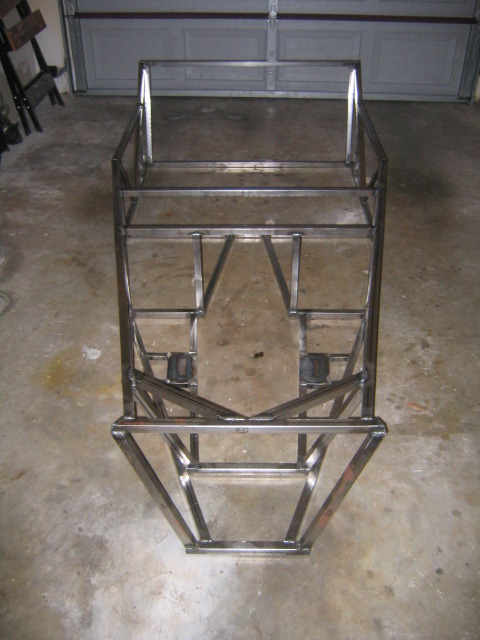
This is what a car looks like in a living room.

...well, a car frame anyway. It's pretty small for car-- but it makes a large piece of furniture.


Also, here's a stair update:

The risers have been pulled off, making them even more treacherous:


The treads have been sanded and stained:


12/12/2006

Hey, what'a ya know... a new post!

Here are some of the most recent pictures. These guys mount between the engine mount platforms on the frame and the actual engine mounts. I built them out of 1/8" plate.


From below when mounted to the frame. I'll need to grind away a little bit of that weld so that the washers will fit flush against the frame.


Another view from the bottom, this time from the rear a little bit.


This is one of the reasons why I haven't been making a lot of progress on the 7 recently. Those new steps I made have to go where I ripped up the old ones. Thanks for the router Dad.


11/02/2006

New pictures, for real!

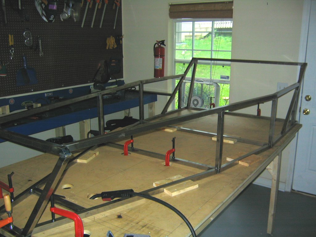
Ha, you didn't think the new camera was going to make it, did you?! Actually I wasn't too sure either. But it turns out I didn't end up getting ripped off. So here's the frame so far:


You can see that the enigne bay is framed out pretty nicely.


I've cut out a space for the transmission and added more vertical supports.


Here's the front end. It's all braced up and ready to go. This is where the inboard ends of the front A-arms are going to mount.


The engine bay from above. Note the engine mount platforms.


A close-up of one of the enigine mount platforms.


Test fitting the engine... and the driver!

10/18/2006

New camera test

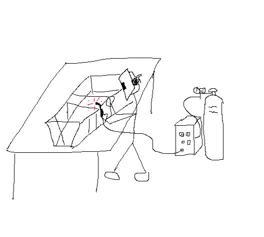
Here's an action shot of me working on the frame. Aren't the images from this new camera so life-like?

10/16/2006

Alright, it's time to get back to work.

Well, actually I have been working... just a little slowly. Let's call it "methodically." The frame has been getting heavier as it gradually gets new parts. I've ordered a new camera-- hopefully it should be here by next week so I can finally post some more pictures.

Also, I've run through my first spool of welding wire. Some more should be here by the end of the week.

9/14/2006

Arrrrgh! My camera is busted.

Oh, here's the problem right here: it says Made in Japan. "But Doc," you might say, "all the best stuff is made in Japan." Unbelievable! But lets hope the made-in-Japan engine works out better than the camera.

Anyway, what I've been doing is adding triangulation members to the frame. These pieces fit diagonally into the frame I've built so far to make it more rigid. Also I've been test fitting the engine in the frame. I've gotten a new transmission mount and my new engine mounts should be here today.

Hopefully soon I'll be able to mount the engine in the frame and start it up.

9/03/2006

My engine is here!

After some confusion with the shipping company, my engine has arrived from Japan Motor Import. It seems to be in decent shape.

The shippers (Yellow Transportation) were kind of giving me the runaround-- telling me that they had "lost" it, but that it hadn't been that long yet (so presumably I, and they, should wait a little longer befor getting too concerned). The guy I talked to at JMI called the shippers for me and got them straightened out.


Here it is-- the engine and tranmission on the hoist in my garage:


From the other side:


From the front. A lot of this stuff is going to go. I'm not going to need either the power steering pump or the A/C compressor, or this big honkin' fan. I'll use an electric fan mounted to the radiator.


The intake manifold and throttle body assembly:


The transmission:


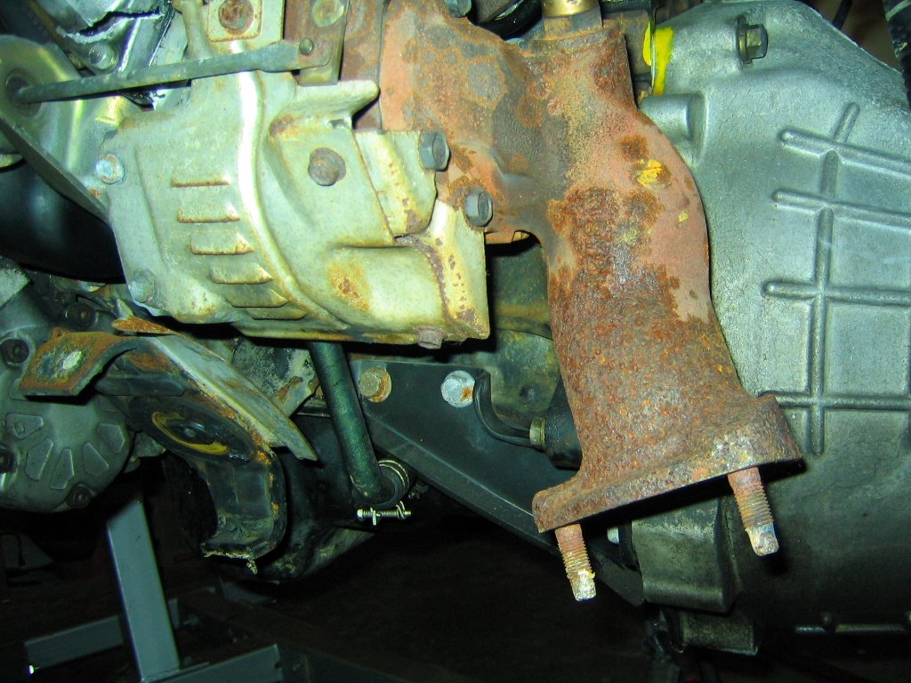
The exhaust outlet from the turbo. The turbo is hidden behind the heat shield. Hmm... that cracked thing in the upper left isn't good. It's the outlet from the compressor side of the turbo-- I'm going to have to make a new one of those...


The underside of the engine. That oil pan took a bit of a beating during shipment.


The ECU:


Air filter and mass airflow sensor (MAF):

8/20/2006

A change of plans

Alright, the plan has changed a little bit. Originally I was going to disassemble the 240sx to use the KA24DE engine, as well as a few other donor parts. But dismantling a car (in addition to building one) seems like a lot of extra work-- especially only for the engine and only a few other parts.

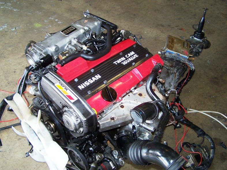
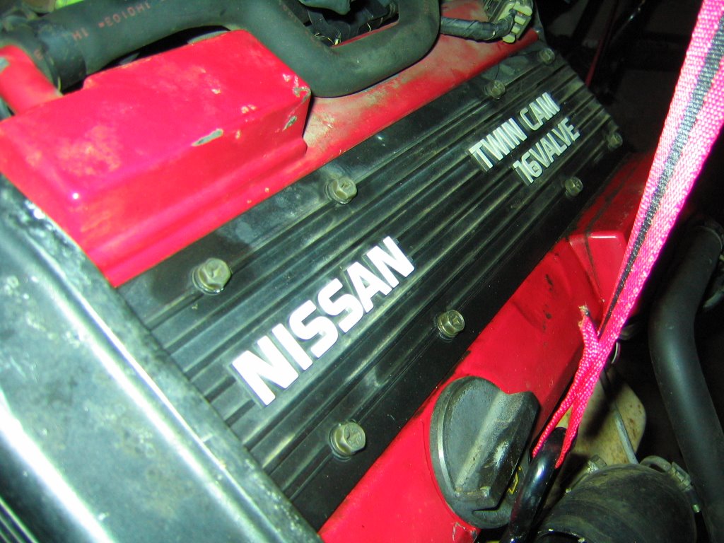
Today I bought another engine to use instead-- a CA18DET. It's lighter and more powerful than the KA24DE. It's got a factory turbo too :) It also comes with a five speed transmission.

Here it is:


CA18DET Specs:
  • 1.8L Inline 4
  • Horsepower: 173 @ 6400RPM
  • Torque: 166 lb-ft @ 4000RPM
  • Garrett T25 turbocharger
  • ~7500 RPM redline
  • Dual overhead cams, 16 valves
  • iron block, aluminum head

It's starting to look like something...

So here's the frame so far. It's starting to look more like a car.


All these pieces are tack welded. I started fully welding some of the joints-- wow, this is going to be a lot of welding.