Oh, here's the problem right here: it says Made in Japan. "But Doc," you might say, "all the best stuff is made in Japan." Unbelievable! But lets hope the made-in-Japan engine works out better than the camera.
Anyway, what I've been doing is adding triangulation members to the frame. These pieces fit diagonally into the frame I've built so far to make it more rigid. Also I've been test fitting the engine in the frame. I've gotten a new transmission mount and my new engine mounts should be here today.
Hopefully soon I'll be able to mount the engine in the frame and start it up.
9/14/2006

9/03/2006
My engine is here!
After some confusion with the shipping company, my engine has arrived from Japan Motor Import. It seems to be in decent shape.
The shippers (Yellow Transportation) were kind of giving me the runaround-- telling me that they had "lost" it, but that it hadn't been that long yet (so presumably I, and they, should wait a little longer befor getting too concerned). The guy I talked to at JMI called the shippers for me and got them straightened out.
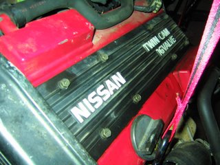
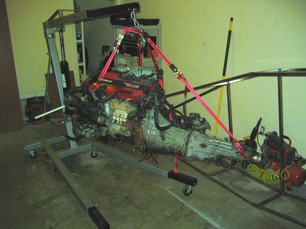
Here it is-- the engine and tranmission on the hoist in my garage:

From the other side:
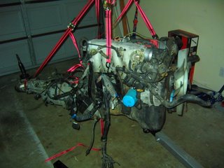
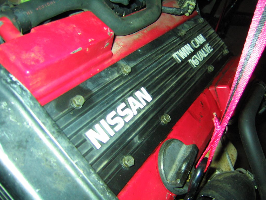
From the front. A lot of this stuff is going to go. I'm not going to need either the power steering pump or the A/C compressor, or this big honkin' fan. I'll use an electric fan mounted to the radiator.
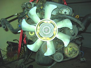
The intake manifold and throttle body assembly:

The transmission:

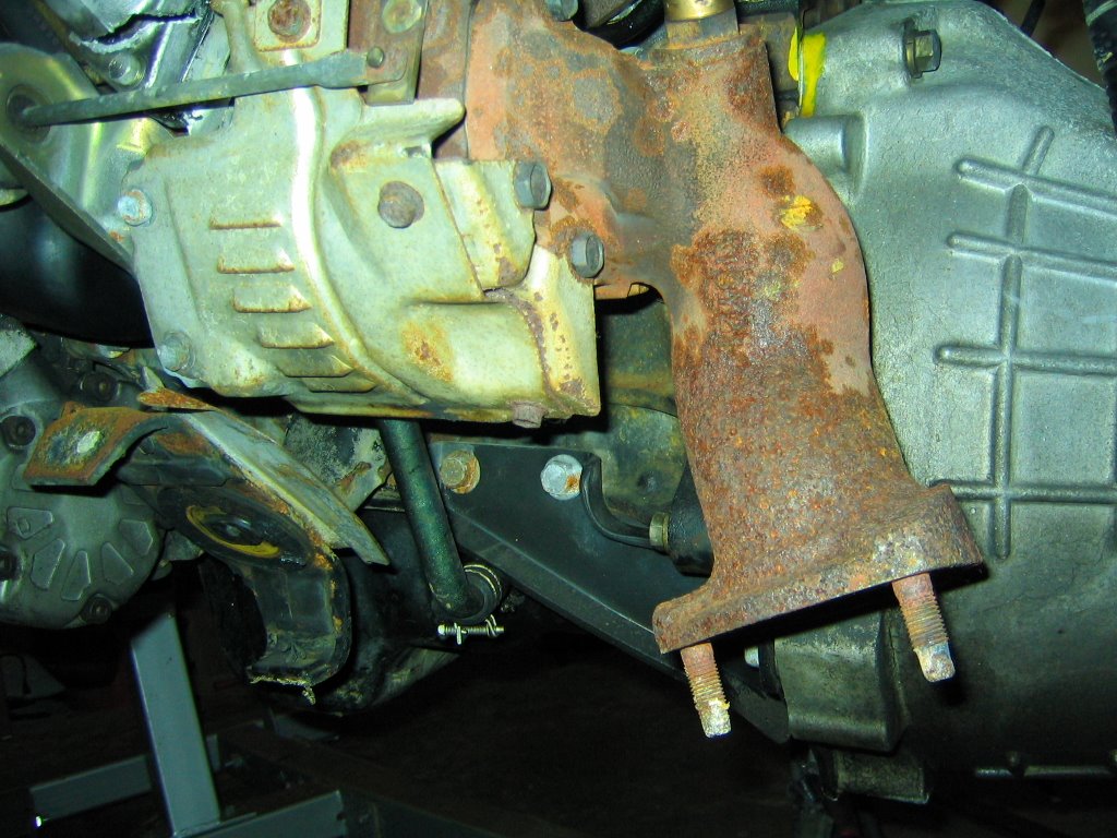
The exhaust outlet from the turbo. The turbo is hidden behind the heat shield. Hmm... that cracked thing in the upper left isn't good. It's the outlet from the compressor side of the turbo-- I'm going to have to make a new one of those...

The underside of the engine. That oil pan took a bit of a beating during shipment.

The ECU:

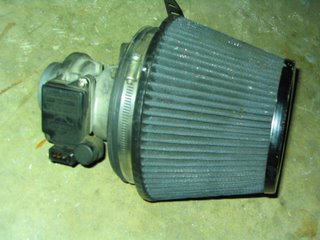
Air filter and mass airflow sensor (MAF):
The shippers (Yellow Transportation) were kind of giving me the runaround-- telling me that they had "lost" it, but that it hadn't been that long yet (so presumably I, and they, should wait a little longer befor getting too concerned). The guy I talked to at JMI called the shippers for me and got them straightened out.
Here it is-- the engine and tranmission on the hoist in my garage:
From the other side:

From the front. A lot of this stuff is going to go. I'm not going to need either the power steering pump or the A/C compressor, or this big honkin' fan. I'll use an electric fan mounted to the radiator.

The intake manifold and throttle body assembly:

The transmission:

The exhaust outlet from the turbo. The turbo is hidden behind the heat shield. Hmm... that cracked thing in the upper left isn't good. It's the outlet from the compressor side of the turbo-- I'm going to have to make a new one of those...
The underside of the engine. That oil pan took a bit of a beating during shipment.

The ECU:

Air filter and mass airflow sensor (MAF):

8/20/2006
A change of plans
Alright, the plan has changed a little bit. Originally I was going to disassemble the 240sx to use the KA24DE engine, as well as a few other donor parts. But dismantling a car (in addition to building one) seems like a lot of extra work-- especially only for the engine and only a few other parts.
Today I bought another engine to use instead-- a CA18DET. It's lighter and more powerful than the KA24DE. It's got a factory turbo too :) It also comes with a five speed transmission.
Here it is:

CA18DET Specs:
Today I bought another engine to use instead-- a CA18DET. It's lighter and more powerful than the KA24DE. It's got a factory turbo too :) It also comes with a five speed transmission.
Here it is:
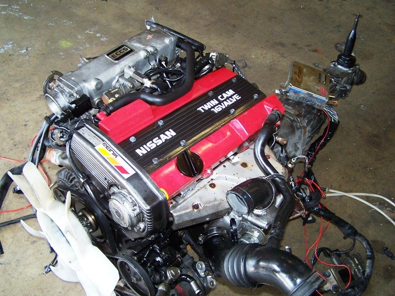
CA18DET Specs:
- 1.8L Inline 4
- Horsepower: 173 @ 6400RPM
- Torque: 166 lb-ft @ 4000RPM
- Garrett T25 turbocharger
- ~7500 RPM redline
- Dual overhead cams, 16 valves
- iron block, aluminum head
It's starting to look like something...
So here's the frame so far. It's starting to look more like a car.

All these pieces are tack welded. I started fully welding some of the joints-- wow, this is going to be a lot of welding.

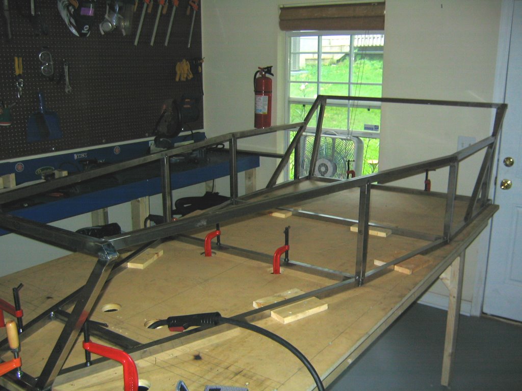
All these pieces are tack welded. I started fully welding some of the joints-- wow, this is going to be a lot of welding.

8/10/2006
The Rear Bulkhead
This is the rear bulkhead. It'll form the back of the passenger compartment. Most of these joints are just tack welded at this point.

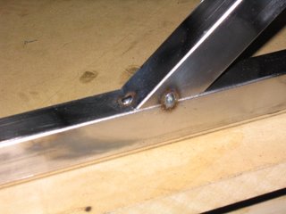
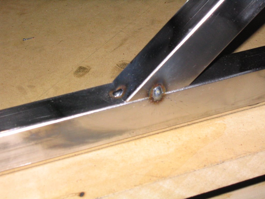
Here are some tack welds up close:
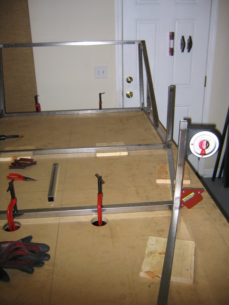
Here you can see me using the magnetic angle gauge on this frame piece. This way I can make sure that these uprights are perpendicular to the base before tack welding them into position.


Here are some tack welds up close:
Here you can see me using the magnetic angle gauge on this frame piece. This way I can make sure that these uprights are perpendicular to the base before tack welding them into position.
7/31/2006
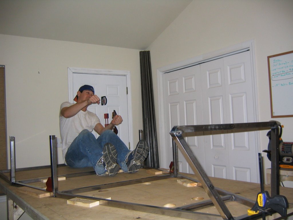
Marty, you're just not thinking 3rd dimensionally!
These are the pieces for the front end. These don't go together quite flat. The top piece actually gets assembled several inches rearward of the bottom piece. The diagonals are cut with compound and angles to accomodate this arragement. This is going to require some more complicated jigging.
Here are some pieces after the ends have been cleaned up. I've been using a wire wheel on the surfaces to welded, followed by a through wipe-down with acetone. It'll keep the welds from getting contaminated. This part can take a while (and it's not as exciting as the welding either), but it's all about the prep.

Here they are all jigged up.

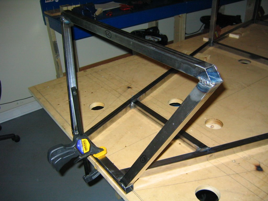
The front end "in situ."

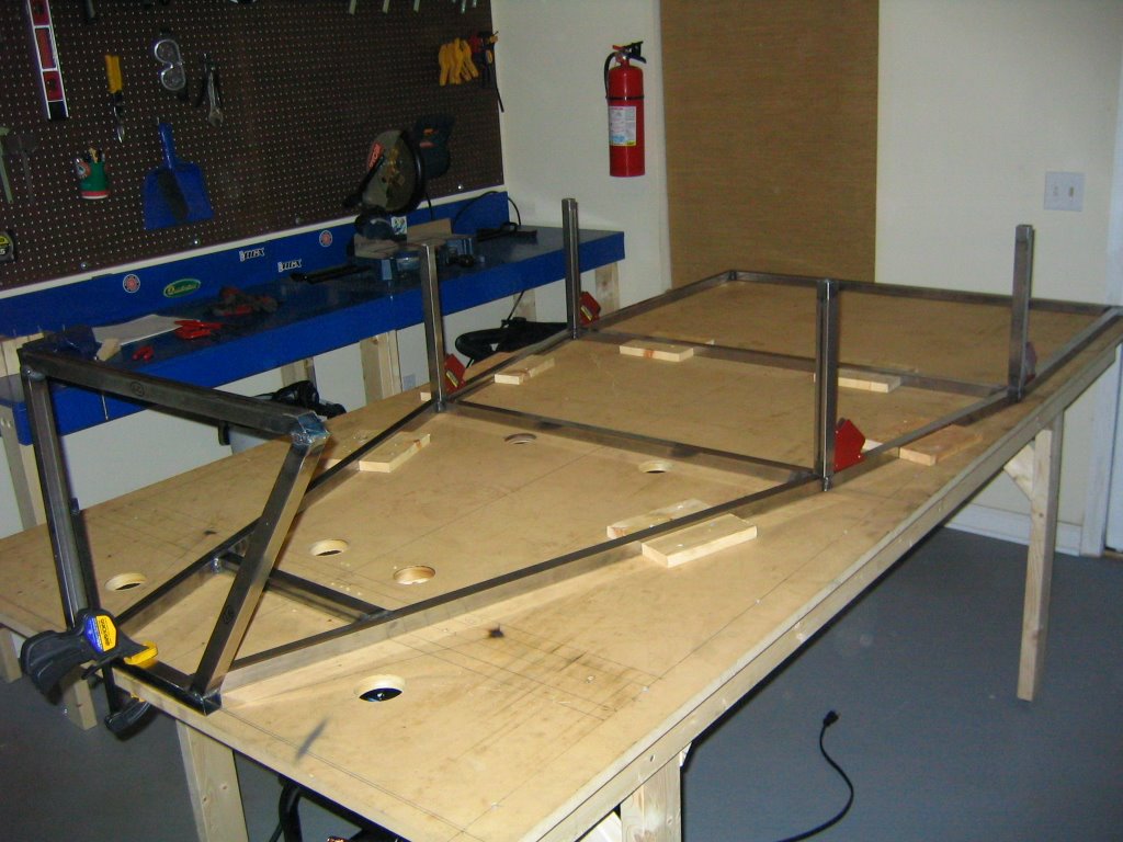
Here it is: the third dimension. I finally started to build up. I've also placed several other vertical pieces here using right angle magnets. None of these are welded yet. I'll tack 'em in soon.
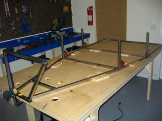
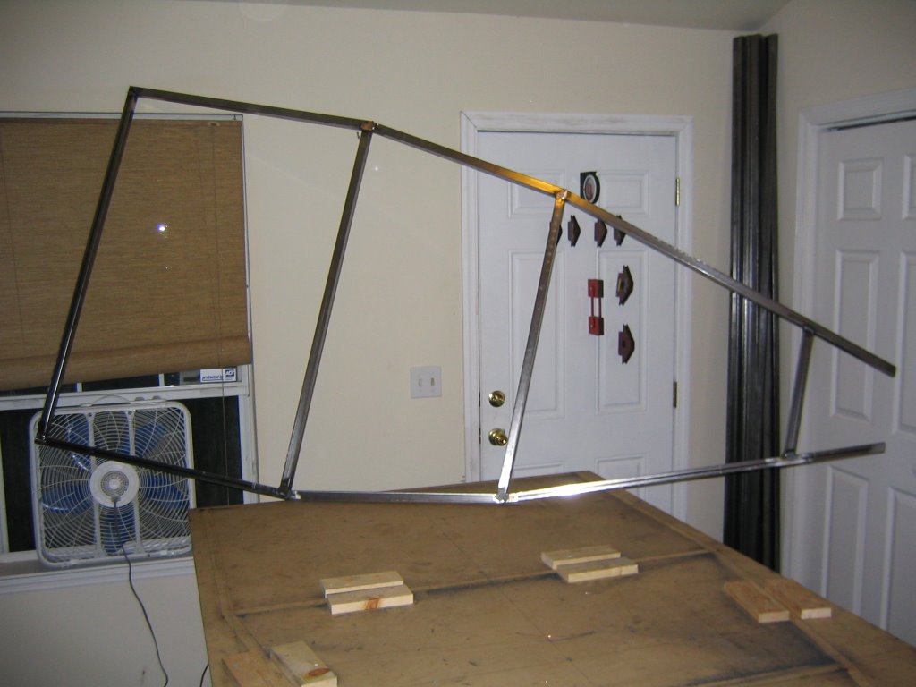
A view from the drivers seat... vroom.

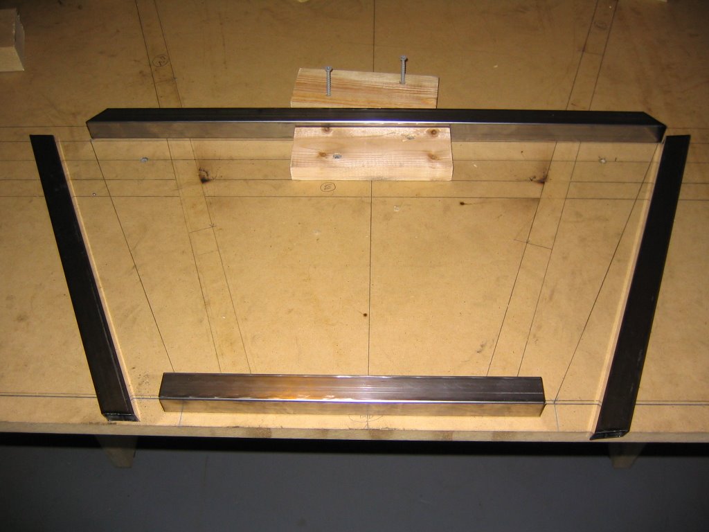
Here are some pieces after the ends have been cleaned up. I've been using a wire wheel on the surfaces to welded, followed by a through wipe-down with acetone. It'll keep the welds from getting contaminated. This part can take a while (and it's not as exciting as the welding either), but it's all about the prep.
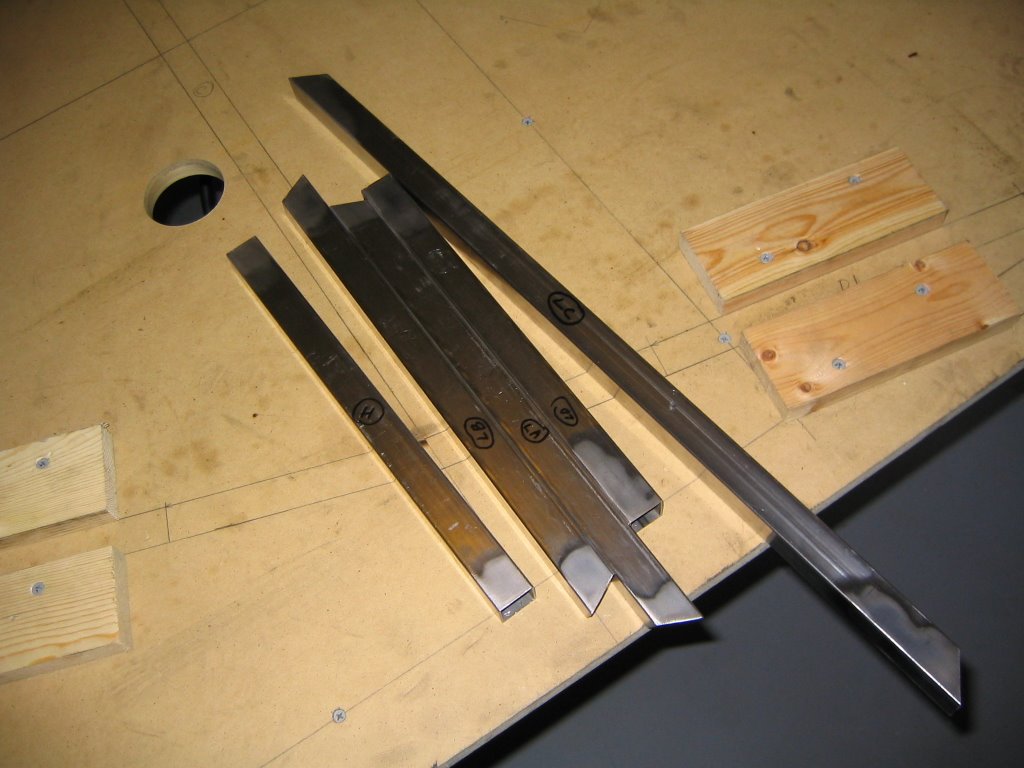
Here they are all jigged up.

The front end "in situ."
Here it is: the third dimension. I finally started to build up. I've also placed several other vertical pieces here using right angle magnets. None of these are welded yet. I'll tack 'em in soon.
A view from the drivers seat... vroom.

7/19/2006
Look ma... no clamps!
The bottom of the frame has been fully welded.

Next: It's on to the front end assembly. Plus some shop cleanup-- grinding makes a real mess.
Next: It's on to the front end assembly. Plus some shop cleanup-- grinding makes a real mess.
7/10/2006
The frame is starting to come together...literally.
Note the fire extinquisher on the wall. It the most expensive one they have at Home Depot.

But back to the car: I've cut all of the peices for the bottom portion of the frame...

And clamped 'em up so they won't move when I weld them.


But back to the car: I've cut all of the peices for the bottom portion of the frame...
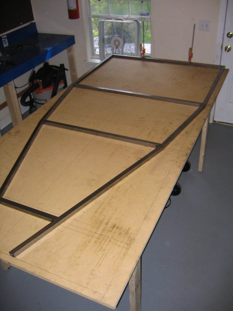
And clamped 'em up so they won't move when I weld them.

7/01/2006
My frame arrived yesterday
Here it is: 16 gauge 1" square mild steel tubing.
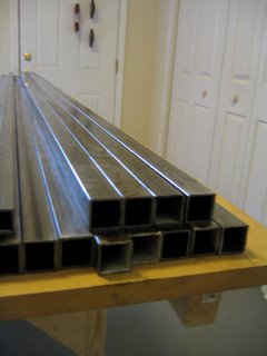
Some assembly required...

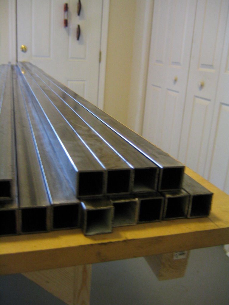
Some assembly required...

6/30/2006
The Shop
I need a place to build this thing... so I set myself up a workshop. Along the wall those are a couple of 4' x 2' tables.
In the forground is a 8' x 4' table that I'm going to build the frame on. It also doubles as a guest bed.

Check out my sweet new MIG welder...

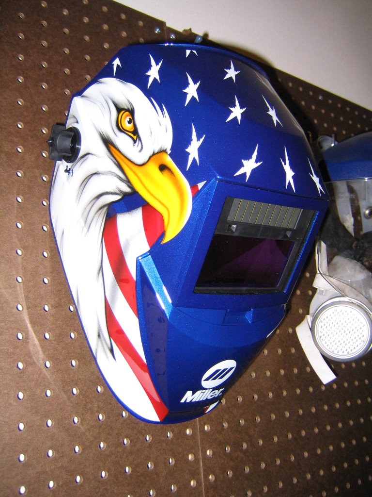
...and my new welding helmet. Don't tread on me.
The beginning
So this is my 240sx. Don't be fooled-- this is its good side.

I'm going to turn it into something like this:
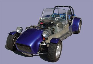
Edit (9/14/2006): No longer am I going to use any part of my 240 for the 7. Why? Well, let me break it down for you.

I'm going to turn it into something like this:

Edit (9/14/2006): No longer am I going to use any part of my 240 for the 7. Why? Well, let me break it down for you.
- Engine - too heavy, too underpowered, too old.
- Front wheel uprights/spindes - they're designed for a MacPherson strut setup. Since I'm going to make my own custom double wishbone suspension, I'd have to modify the upper mount on the spindle. Miata uprights will work great instead.
- Rear wheel uprights - also are not going to be great for my custom built suspension. They have mounting points that come off at odd angles, and require compliance in the bushings for the suspension to travel correctly. Miata rear uprights will also work better.
- Differential - it's open. I want a limited slip differential.
- Steering - I'm not sure, but I'd imagine that the steering rack is going to be too wide to fit. It'll be easier to buy a new one.
Subscribe to:
Posts (Atom)